Relay Starter Replacement (3100-watt Inverters)
![]() Updated
by
Juan Velez
Updated
by
Juan Velez
190513-60-50-1
The following bulletin covers the following models: 75537i, 100204, 100261, 100262, 100263, 100264, 100477 - Dual Fuel, Electric-Start, or Wireless Remote-Start 2800-watt + inverters.
*Specification, descriptions, and illustrations are as accurate as known at the time of publication but are subject to change without notice.
- To reduce the risk of injury, the user must read and understand the operator's manual before using this product.
- DO NOT make any adjustments to the generator without first stopping the engine, turning all the switches to the "OFF" position, closing the fuel valve, and disconnecting the spark plug wire.
- Burns from hot parts - let the engine cool for 30 minutes before touching any hot parts.
- Injury from moving parts.
- To reduce the possibility of fire or explosion, be careful when working around gasoline. Keep cigarettes, sparks, and flames away from all fuel-related parts.
Tools Required
Tool | Size |
Ratchet | 3/8" |
Sockets | 7 mm, 8 mm, 10 mm |
Pliers | Box nose |
Phillips Screwdriver | #2 |
Crescent Wrenches | 7 mm, 8 mm |
Empty Gas Container | Minimum two gallons |
Nitrile Gloves | |
*3 - Containers or boxes for parts | Small to Medium |
*Containers or boxes will help organize/identify parts when reassembling.
- Ensure the Fuel Valve, Battery, and Start switches are in the "OFF" positions. (Panel illustrated below is from model 75537i)
Visual
See below.
- Remove the two Phillips screws from the battery maintenance cover and pull on the rubber tab to access the battery. Un-clip the pinch rubber and slide the battery back to access cables. Pull back on the protective boots to expose the battery bolts and, using a 10 mm wrench or socket, remove the Black (-) negative cable first and then remove the Red (+) positive cable. (Put all battery parts into a tray and label it "Battery Parts.")
Visual
See below.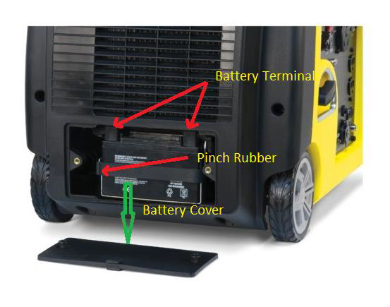
- Remove the two Phillips screws to remove the access panel.
Visual
See below.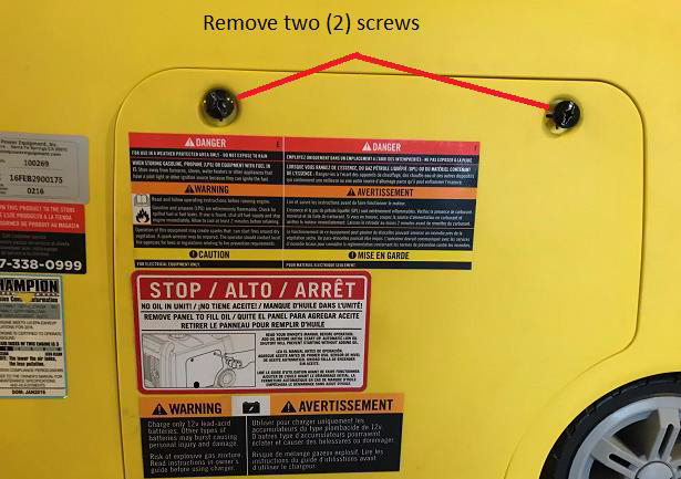
- Gently pull the spark plug cap by firmly grasping the spark plug insulator at the base. Leave it disconnected while working on the unit.
Visual
See below.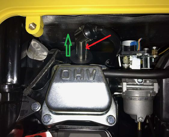
- Remove the clear or pink carburetor drain hose from the drain hole in the base of the enclosure and extend the hose to the exterior and direct it into your gasoline container. Turn the main fuel valve to the "ON" ("gasoline" position for Dual-Fuel units) and with the hose securely positioned into your gasoline can, loosen the drain screw only enough until you see gas flowing. After the fuel tank is completely empty, close the drain screw, turn the fuel valve "OFF," and insert the drain hose back into the drain hole of the base of the enclosure.
Visual
See below.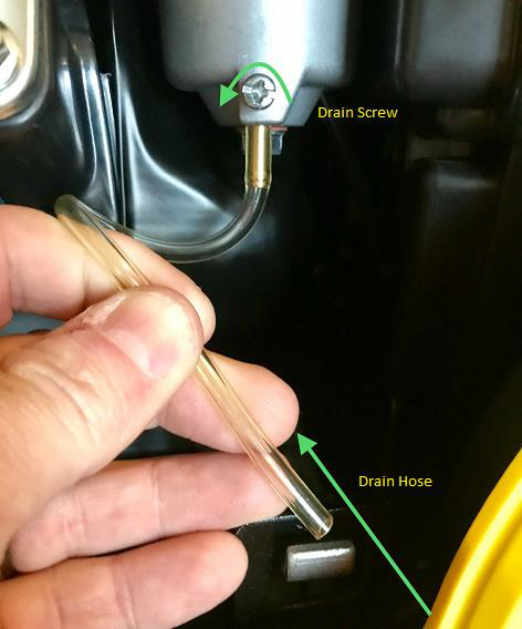
- On the top handle of both side, with a Phillips screwdriver, remove the three Phillips screws facing the gas cap.
Visual
See below.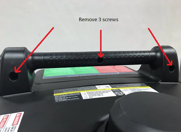
- Separate the handle along the center seam and pull downwards toward the top of the unit. (Put all parts into a box and label it "Top/Handle Parts.")
Visual
See below.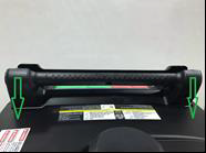
- Located on the right side of the metal frame, remove the two bolts with a ratchet and 10 mm socket. (Put all parts into a box and label it "Right Side Parts.")
Visual
See below.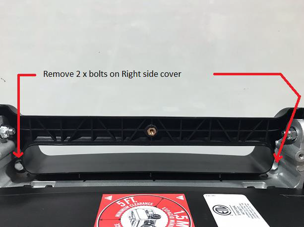
- With a Phillips screwdriver, remove the two screws on each side and then, with a ratchet using a 10 mm socket, remove the two shoulder bolts at the bottom.
Visual
See below.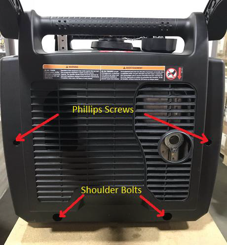
- Remove the right side cover (Handle side). (Place hardware into a tray already labled "Right Side Cover.)
Visual
See below.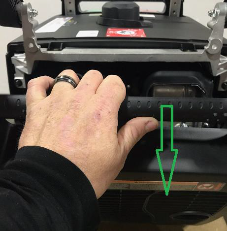
- Unscrew the gas cap and remove the Phillips screw. Place the gas cap to the side. (We suggest you thread the screw back into the cap, so as not to misplace.)
Visual
See below.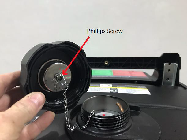
- Remove the top cover by removing the four bolts (two on each side) with a 10 mm socket. (Put all the parts into a box labeled "Top/Handle Parts.")
Visual
See below.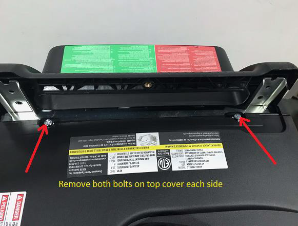
- Gently push up on the top cover; the top will unsnap out of place. Replace the gas cap on the tank.
Visual
See below.
- Remove the four fuel tank bolts with a 7 mm socket. Remove the rubber hose on the top by gently twisting and pulling it with your fingers. (Put all the parts into a box labeled "Top/Handle Parts.")
Visual
See below.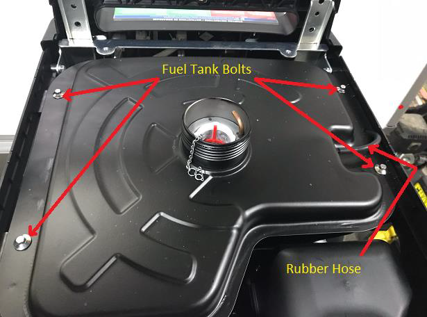
- Gently lift-up on the gas tank and locate the hose clamp securing the fuel line in place. (Make sure the gas tank is empty if you have not already done so in step #6 before removing the fuel line.) Using your pliers, pinch the clamp to expand it and gently wiggle the fuel link and clamp it off. Once removed (gas cap on the tank), place the tank in a safe location, away from cigarettes, sparks, and flames.
Visual
See below.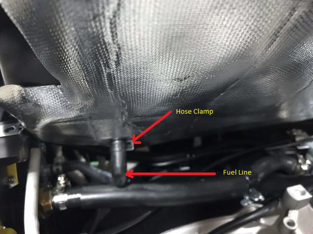
- Loosen the choke cable clamp screw and loosen the cable wire clamp using a 7 mm and 8 mm wrench. Remove the choke cable from the pinch bolt, and allow the cable to lay loosely, so we can remove the front panel in a later step.
Visual
See below.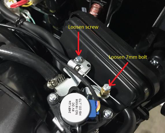
- If a unit is a dual-fuel model, take note of which wires go to which terminals. We suggest you take a picture then disconnect the spade terminals. There are six connections and we only use four, so we recommend you take a picture!
Visual
See below.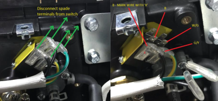
- On the front panel, remove the five screws as indicated. Remove the center screw and pull off the fuel knob and place it to the side. DO NOT lose the small center screw. (Put all parts into a box and label it "Front Panel.")
Visual
See below.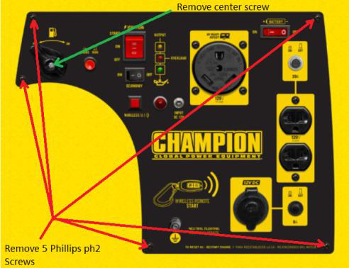
- FOR DUAL-FUEL MODELS ONLY - Remove the five front panel screws as indicated. Holding the fuel knob in the "OFF" position, remove the center screw and pull off the fuel knob and place it to the side. DO NOT lose the small center screw. (Put all parts into a box and label it "Front Panel.")
Visual
See below.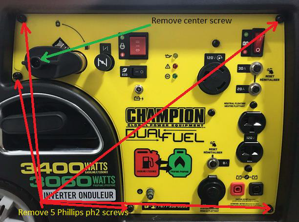
- Once all the screws are removed, gently pull out on the top right-hand corner, and swing out the panel slowly; DO NOT FORCE.
Visual
See below.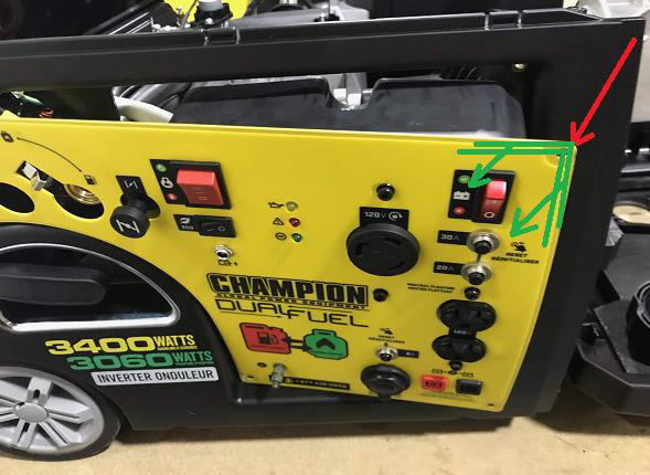
- Located on the inside left front panel below the recoil cord, disconnect the Molex connector from the Rectifier. This will enable you to achieve more room to open the front panel.
Visual
See below.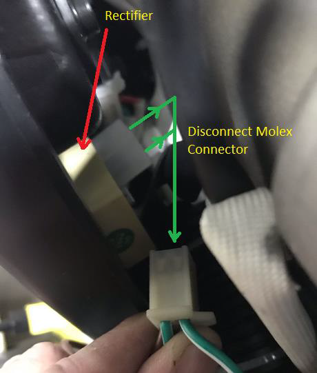
- Directly in front of you, against the engine block, you will see the starter solenoid and starter motor. Inspect the black solenoid wire for damaged wire insulator as shown in the picture. Use electric tape to cover the exposed copper wire and wrap firmly with at least three to four layers.
Visual
See below.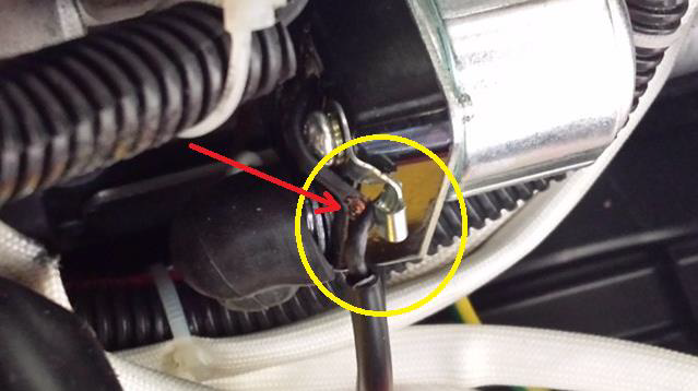
- (A) Remove the factory-installed zip tie and install a new zip tie after creating additional free play on the black solenoid wire. (B) Loosen the vibration support strap to rotate from outward to upward and re-tighten. (C) If replacing the solenoid, remove the single bolt with a 10 mm socket disconnect wires and install new ones. Make sure the cable routing is correct. Reverse these steps for reassembly.
View and download the PDF version here.