Recoil Replacement (3100+ Watt Inverters)
190604-50-10-1 This bulletin covers the following models: 75531i, 75537i, 75555i, 100204, 100233, 100261, 100262, 100263, 100264, 100269, 100396, 100476, 10477, 100523. Please read the instructions c…
Updated
by Juan Velez
190604-50-10-1
This bulletin covers the following models: 75531i, 75537i, 75555i, 100204, 100233, 100261, 100262, 100263, 100264, 100269, 100396, 100476, 10477, 100523.
Please read the instructions carefully and completely before performing the service.
*Specification, descriptions, and illustrations in this technical bulletin are as accurate as known at the time of publications but are subject to change without notice.
SAFETY PRECAUTIONS
- To reduce the risk of injury, user must read and understand the operator’s manual before using this product.
- DO NOT make any adjustments to the generator without first stopping the engine and disconnecting the spark plug wire.
- Burns from hot parts — let the engine cool completely before touching hot parts.
- Injury from moving parts.
- To reduce the possibility of fire or explosion, be careful when working around gasoline. Keep cigarettes, sparks and flames away from all fuel‐related parts.
- Never store the machine with gasoline in fuel tank or carburetor if it isn’t used or drained within 2-4 weeks.
Tools Required
Rachet | 1/4 or 3/8 drive |
Extension | 6 or 12 " |
Sockets | 7 mm, 8 mm, and 10 mm |
Phillips Screwdriver | #2 |
Nitrile Gloves |
- Ensure that the battery switch, start switch, and the fuel valve are all in the "OFF" positions.
Visual
See below.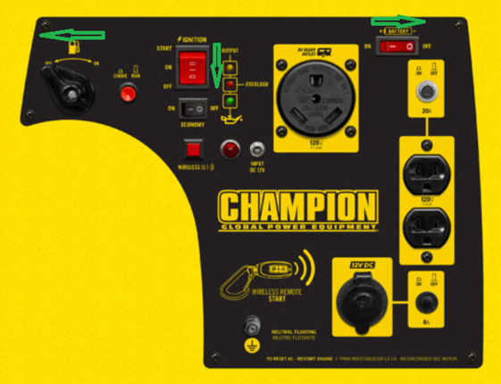
- Remove the two Phillips screws from the battery maintenance cover and pull on the rubber tab to access the battery. Unclip the pinch rubber and slide the battery back to access the cables. Pull back on the protective boots to expose the battery bolts and, using a 10 mm wrench or socket, remove the Black (-) negative cable first and then remove the Red (+) positive cable.
Visual
See below.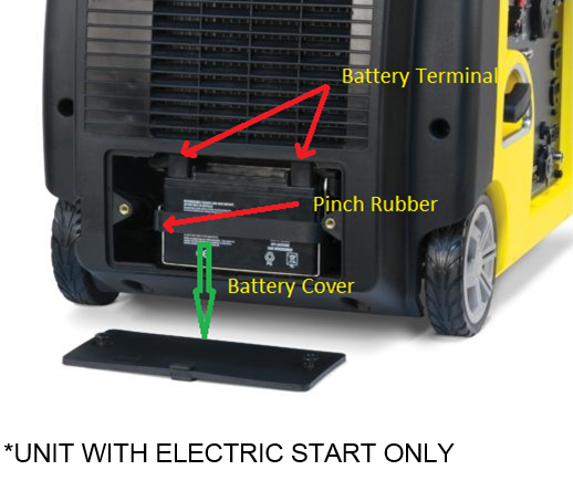
- Remove the two Phillips screws to retract the access panel.
Visual
See below.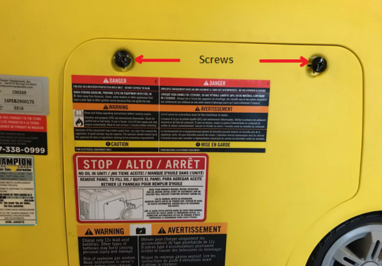
- Gently pull the spark plug cap by firmly grasping the spark plug insulator at the base. Leave it disconnected while working on the unit.
Visual
See below.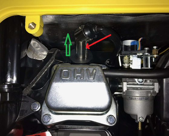
- Remove the three Phillips screws from the left handle.
Visual
See below.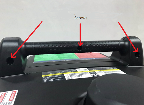
- Separate the handle along the center seam and pull it downwards towards the top of the unit.
Visual
See below.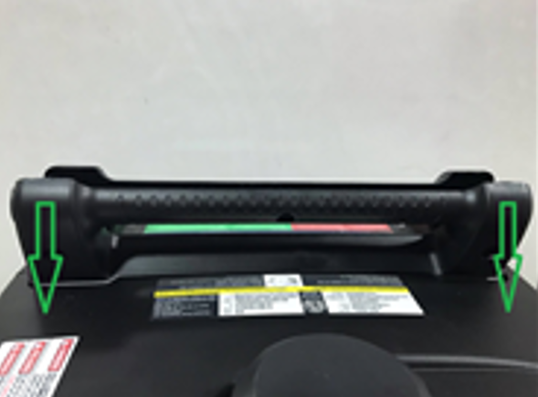
- With a Phillips screwdriver, remove the two screws on each side, and use a rachet with a 10 mm socket to remove the two shoulder bolts at the bottom.
Visual
See below.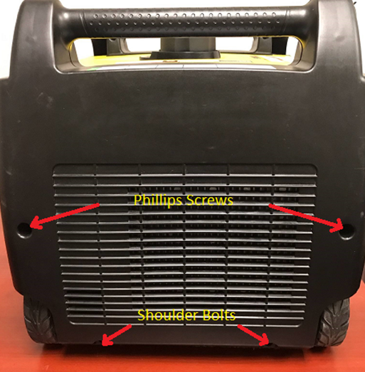
- To remove the left-hand side cover, gently pull away from the right side toward the left just like opening a door. Disconnect both rubber pipes from the carbon canister and then remove the left-hand cover completely. For Electric-Start models, go to step #14.
Visual
See below.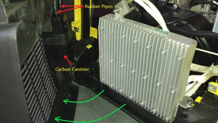
- Lift up the wire clamp and pull it back to release the wires.
Visual
See below.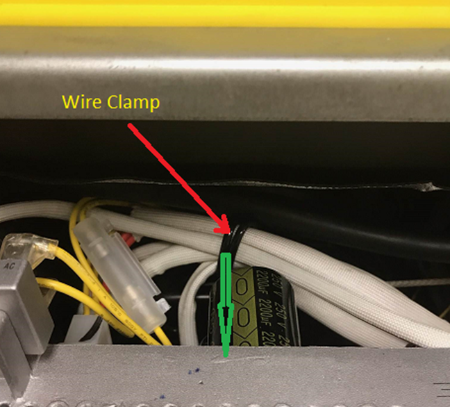
- Remove the two pressure plate bolts with a 7 mm socket.
Visual
See below.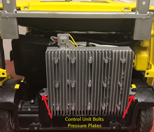
- Once the screws are removed, gently pull upwards on the control unit evenly. DO NOT FORCE.
Visual
See below.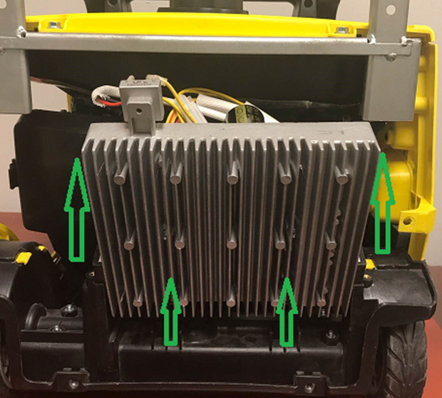
- Place the control unit face down as shown and disconnect the molex connector by squeezing the locking tab and pulling it up.
Visual
See below.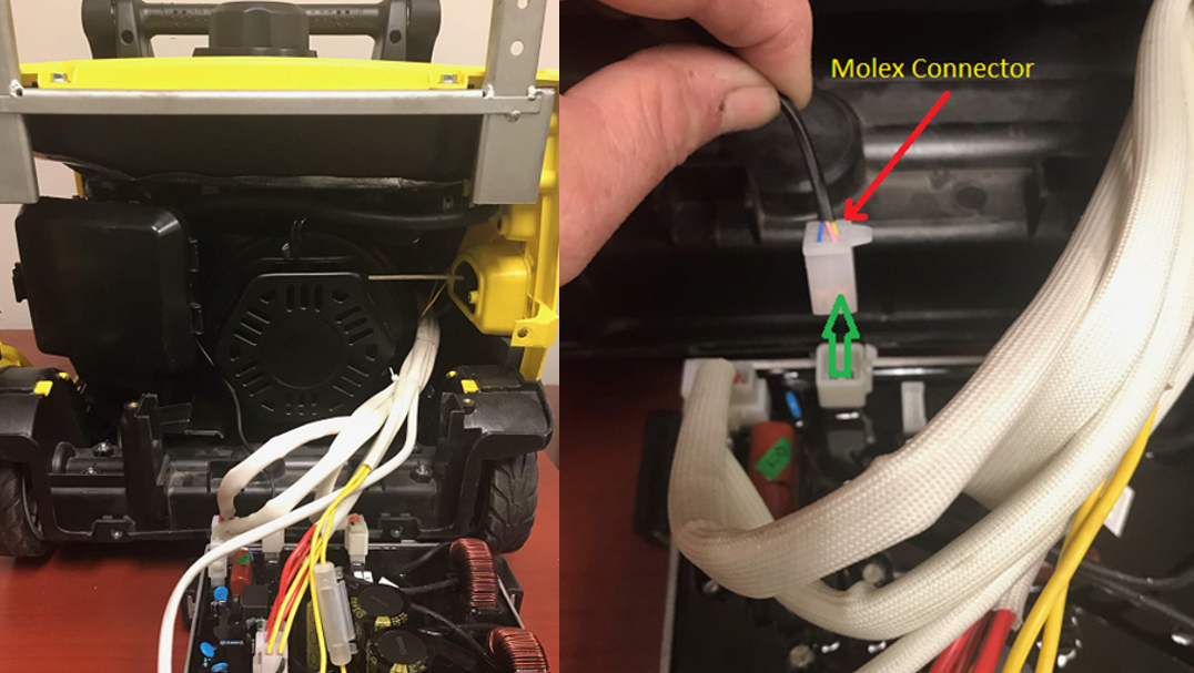
- Move the stepper motor connector off to the left-hand side and move the control unit over to the right. Go to step #19.
Visual
See below.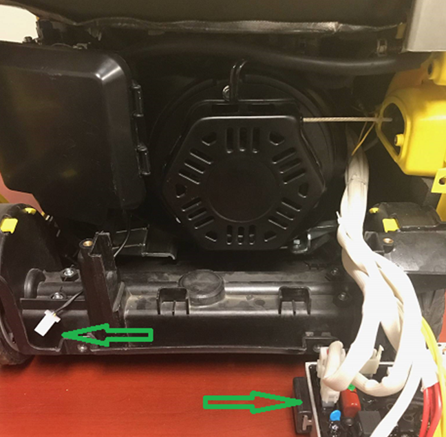
- FOR ELECTRIC START MODELS. Remove the bottom two control holder bolts with a 7 mm socket. Remove the top two control holder bolts on each side with a 10 mm socket.
Visual
See below.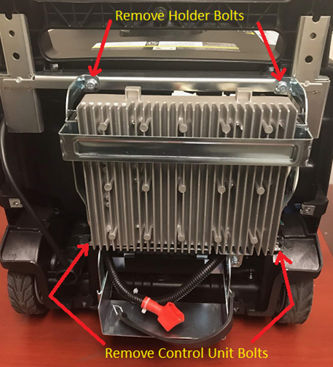
- Disconnect the molex connector with a black insulator wire by squeezing the locking tab and pull it towards inside the unit.
Visual
See below.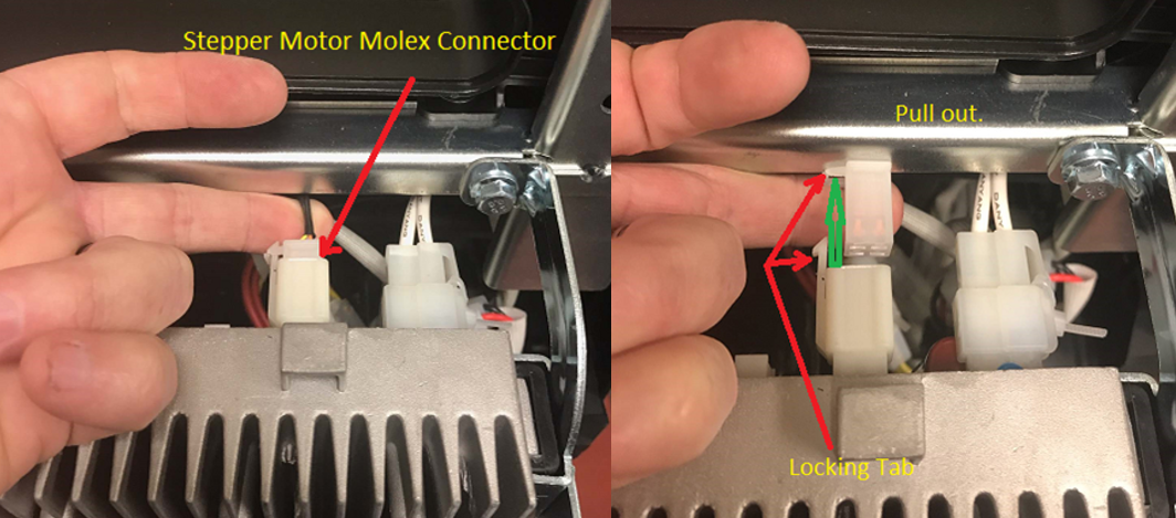
- Lift up the wire clamp and pull it back to release the wires.
Visual
See below.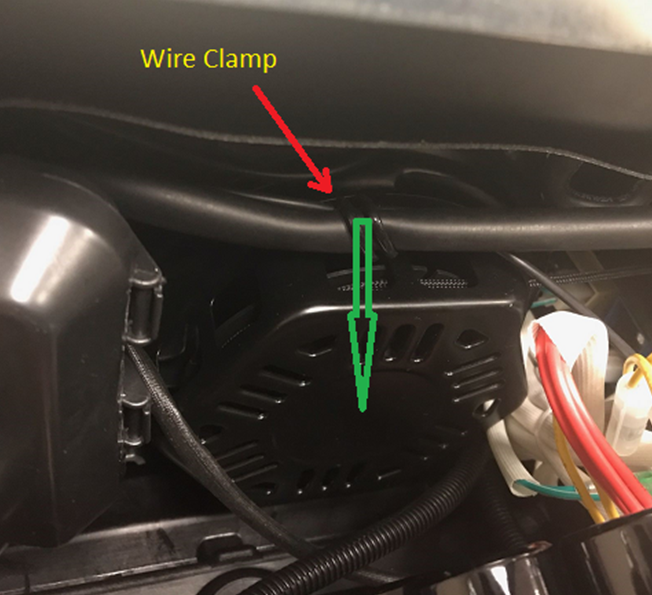
- Move the stepper wire connector off to the left-hand side and pull the control unit down.
Visual
See below.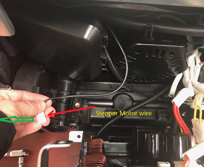
- Place the control unit face down and rotate it 90 degrees as shown. Make sure the stepper motor wire connector is off to the left-hand side as in the previous step.
Visual
See below.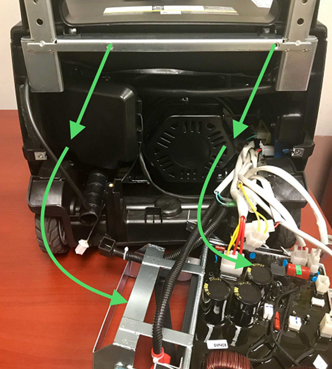
- Remove the two Phillips screws from the guide plate for the recoil rope and handle.
Visual
See below.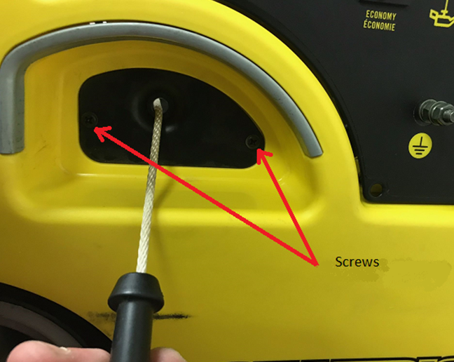
- From the inside, push out on the guide plate. Now twist the guide plate as shown and pull it back through the opening along with the recoil handle.
Visual
See below.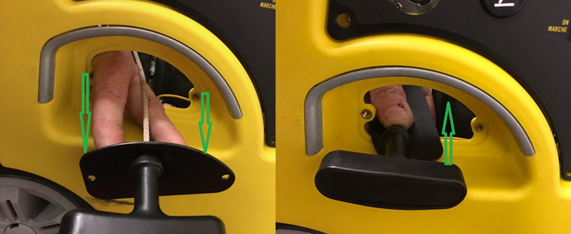
- Remove the wire clamp and the three bolts with a 10 mm socket to remove the recoil assembly. Make sure that the wire clamp is put back at the 12 o'clock position upon installation.
Visual
See below.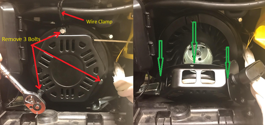
How did we do?
High Altitude Jet Installation (2,800+ Watt Inverters)
Ignition Assembly Replacement for 2000-Watt (Cubed) Inverters