100435 (060-3732-6) 22" Snow Blower - Model Year 17 to model year 18 Conversion
![]() Updated
by
Juan Velez
Updated
by
Juan Velez
181127‐140‐30‐1
This bulletin covers the following models: 100435 (060-3732-6) 22" Snow Blower MY17 only.
Each section is written as if they are done independently. NOTE: If doing all the upgrades together, read each section in its entirety and update as necessary. Chaque section est écrite comme si elles étaient réalisées indépendamment.
- To reduce the risk of injury, the user must read and understand the operator's manual before using this product.
- DO NOT make any adjustments to the snowblower without first stopping the engine, removing the engine key, and disconnecting the spark plug wire.
- Burns from hot parts - let the engine cool for 30 minutes before touching hot parts.
- Injury from moving parts - this machine may pick up and throw objects which can cause serious personal injury. Keep bystanders at a safe distance.
- To reduce the possibility of fire or explosion, be careful when working around gasoline. Keep cigarettes, sparks, and flames away from all fuel-related parts.
- DO NOT run the engine with the belt guard removed.
Upgrade Auger Control Cable Guide
Parts Needed
Part Number | Description | Qty |
23035000125000C | Front Wire Support Seat | 1 |
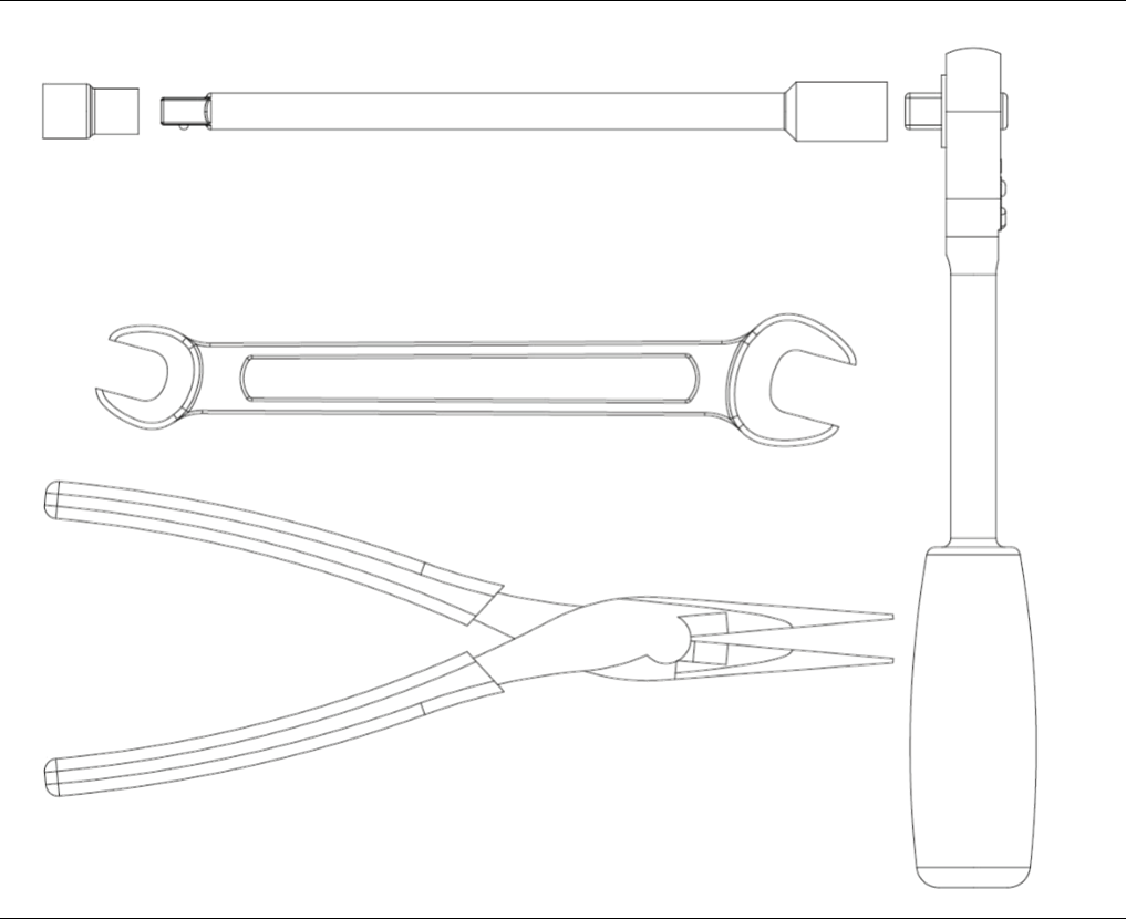
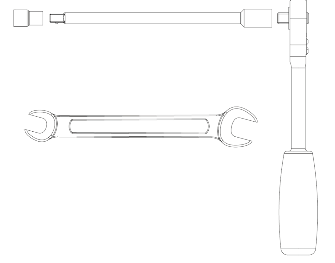
Tools Needed
Tool | Size |
Ratchet and 18” extension | 10 |
Wrench | 10 |
Needle Nose Pliers |
Visual

- Remove the plastic belt cover on the front of the engine by removing the two M6x16 bolts.
Visual
See below.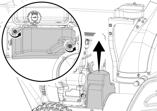
- Remove the clip using needle nose pliers, and the two M8 bolts from the side of the snowblowers.
Visual
See below.
- Replace the Front Wire Support Seat assembly. Reassemble the bolts and torque hardware to 2.2-3.7 ft.-lbs. Replace clip.
Visual
See below.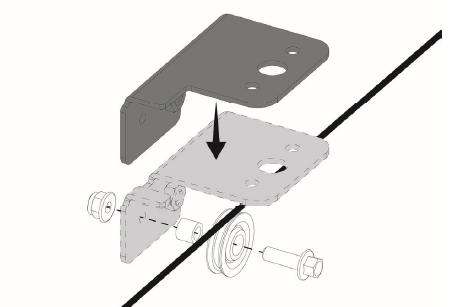
- See your operator's manual section "ADJUSTING AUGER CONTROL CABLE."
Visual
See below.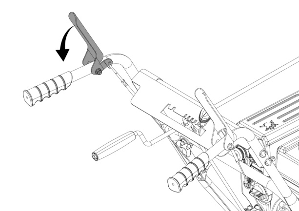
- Install the plastic belt cover using two M6 x 16 bolts set aside from the previous step. Torque until snug. Do not over-tighten or you risk damaging the plastic belt cover. Perform a drive test to confirm everything is in working order.
Upgrade Belt Guard
Visual
- Remove the plastic belt cover on the front of the engine by removing the two M6 x 16 bolts.
Visual
See below.
- Remove one bolt (20 mm) holding the single style belt guard; also remove the similar bolt approximately 4" to the left (See illustration). Place the new dual style belt guard back into place and install the bolts (20 mm/30 mm). NOTE: Pay attention that the that the original side is 20 mm and the new side is 30 mm. Once reinstalled, make sure there is equal distance on both sides between the pulley and the guard. Reassemble the bolts and torque hardware to 13.3-16.2 ft-lbs./18-22Nm.
Visual
See below.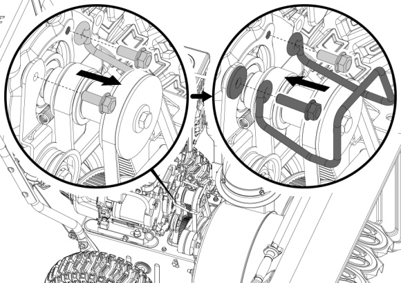
- Once installed, ensure there is equal distance on both sides between the pulley and the guard. (1/16 to 3/16" or 2-5 mm). If the distance needs to be adjusted, carefully use a long socket extension or pry bar to adjust the guard. Be careful not to damage the belt of pulley. DO NOT run the engine with the belt guard removed.
Visual
See below.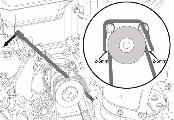
- Install the plastic belt cover using the two M6 x 16 bolts set aside from an earlier step. Torque until snug. Do not over-tighten or you risk of damaging the plastic belt cover. Perform a drive test to confirm everything is in working order.
Upgrade Drive Pulley
Visual
- Remove the plastic belt cover on the front of the engine by removing the two M6 x 16 bolts.
Visual
See below.
- Remove the 20 mm bolt holding the single style belt guard. If your snow blower currently has a single-sided belt guard, please replace it with a double-sided belt guard as part of this repair.
Visual
See below.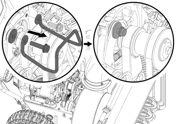
- Remove the pulley as shown.
Visual
See below.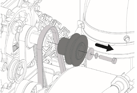
- Assemble the new pulley. Reassemble the bolt and torque hardware to 13.3-16.2 ft-lbs./18-22Nm.
Visual
See below.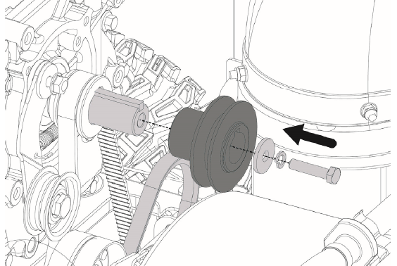
- With the belt properly placed over the auger drive pulley, pull the auger idler pulley back away from the belt and slip the belt inside the pulley. You can pull the recoil to rotate the pulley to help get it seated. DO NOT run the engine with the belt guard removed.
Visual
See below.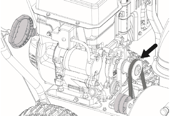
- Place the belt guard back into place and install the 20 mm/30 mm bolts that were removed earlier. NOTE: Pay attention that original side is 20 mm and the new side is 30 mm. Once reinstalled, make sure there is equal distance on both sides between the pulley and the guard. Reassemble the bolts and torque hardware to 13.3-16.2 ft-lbs./18-22Nm.
Visual
See below.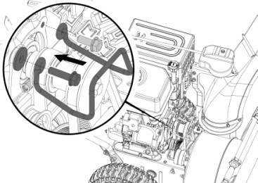
- Once reinstalled, make sure there is equal distance on both sides between the pulley and the guard. (1/16 to 3/16" or 2-5 mm). If the distance needs to be adjusted, carefully use a long socket extension or pry bar to adjust the guard. Be careful not to damage the belt or pulley.
Visual
See below.
- Install the plastic belt cover using the two M6 x 16 bolts set aside from an earlier step. Torque until snug. Do not overtighten or you risk damaging the plastic belt cover. Perform a drive test to confirm everything is in working order.
View and download the PDF version here.