Recoil Replacement (Cube Inverters)
181107-60-50-1 This bulletin covers the following models: 73540i, 73536i, 73535i. 100148, 100489, 100455. Please read the instructions carefully and completely before performing the service. SAFETY P…
Updated
by Juan Velez
181107-60-50-1
This bulletin covers the following models: 73540i, 73536i, 73535i. 100148, 100489, 100455.
Please read the instructions carefully and completely before performing the service.
SAFETY PRECAUTIONS
- To reduce the risk of injury, user must read and understand the operator’s manual before using this product.
- DO NOT make any adjustments to the generator without first stopping the engine and disconnecting the spark plug wire.
- Burns from hot parts — let the engine cool completely before touching hot parts.
- Injury from moving parts
- To reduce the possibility of fire or explosion, be careful when working around gasoline. Keep cigarettes, sparks and flames away from all fuel‐related parts.
- Unscrew the four bolts holding the handle and remove the handle assembly.
Visual
See below.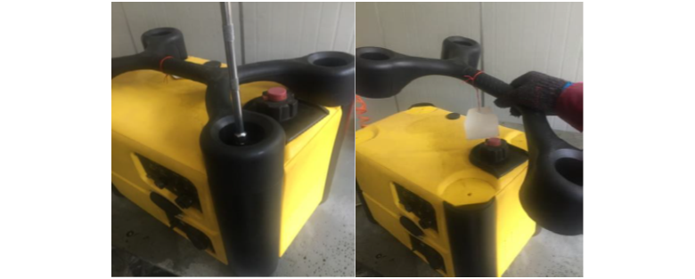
- Unscrew the fuel tank cap and remove the upper cover. NOTE: After removing the upper cover, re-screw the fuel tank cap to prevent gasoline from escaping.
Visual
See below.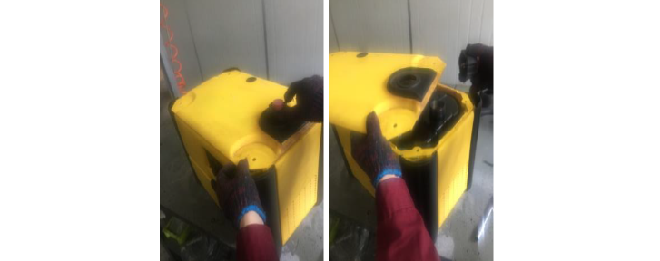
- Remove the four corner panels.
Visual
See below.
- Remove the screws to take off the right cover. Repeat this for the left cover.
Visual
See below.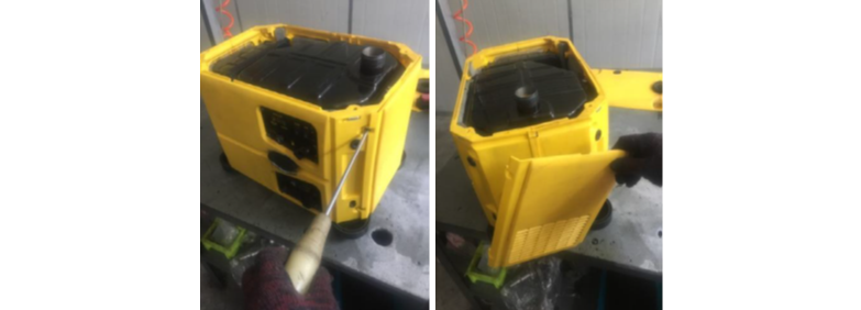
- Unscrew the three bolts that hold the fuel tank.
Visual
See below.
- Remove all the screws and bolts of the front and rear covers, and then take off the rear cover assembly.
Visual
See below.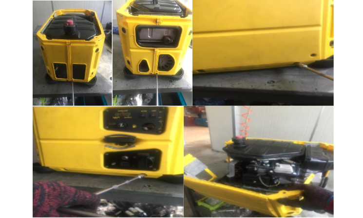
- Remove the screw inside the fuel ON/OFF switch. Loosen the clamp of the fuel hose at the carburetor inlet nozzle to pull out the fuel hose, and then remove the fuel tank.
Visual
See below.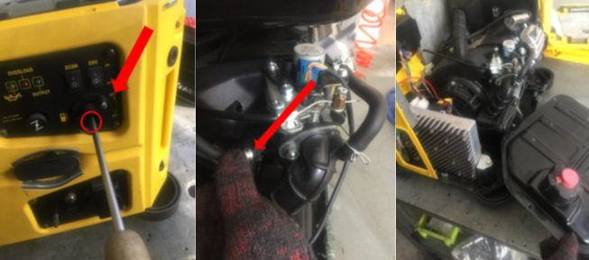
- Pull out some length of the rope from the recoil pulley and secure the stop-knot at the recoil cover end. Remove the recoil handle.
Visual
See below.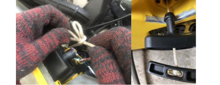
- Unscrew the bolts of the controller module, remove the rectifier on the controller module, and then unplug all of the module's connectors and remove it.
Visual
See below.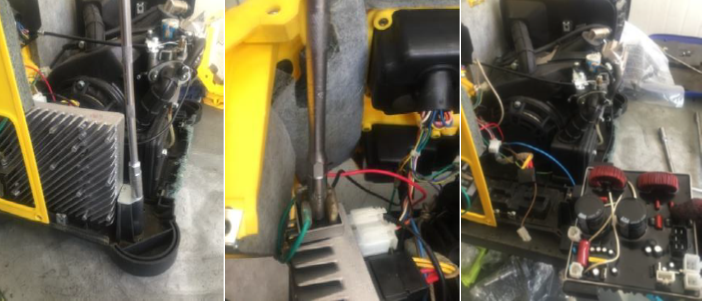
- Unscrew the recoil assembly and replace.
Visual
See below.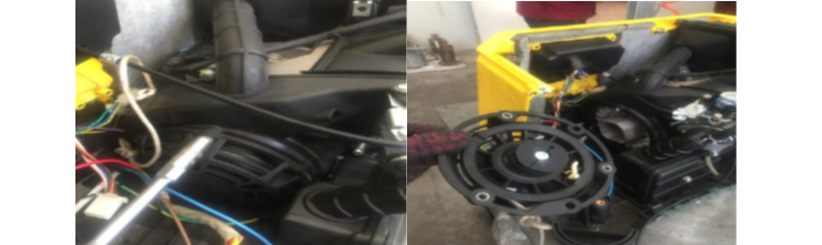
- Put the new spring into the pulley if needed to replace a new spring.
Visual
See below.
- Put the new rope into the pulley and secure it with a stop-knot. Next, rotate the rope clockwise (spring side towards you [about 3.5 turns]) until the rope aligns with the open slot on the outer edge of the pulley.
Visual
See below.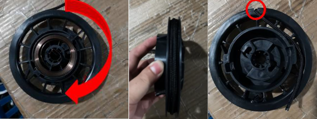
- Apply lubricant or grease to the shaft of the recoil cover and inset the pulley to the recoil cover.
Visual
See below.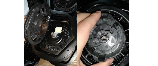
- Pull the rope into the slot and take the loose part of the rope inside the pulley and rotate the pulley about three turns (counterclockwise) until the tension spring resists. Hold the pulley from reversing until the rope is ready to wind back onto the pulley. Feed the rope out to the hole of the recoil cover and pull it through the guide hole on the outside of the recoil cover. Place the guide plate/pull handle on the rope and secure it with a stop-knot.
Visual
See below.
- Place the two detent springs as shown.
Visual
See below.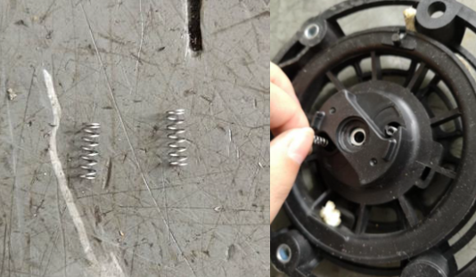
- Place the two plastic detents into the spring positions with some lubricant. NOTE: The detents must press the springs when installing.
Visual
See below. - Install the hoop onto the plastic press plate, and then put the plastic press plate onto the detents. NOTE: The salient of detents must snap into the guide slot of the press plate.
Visual
See below.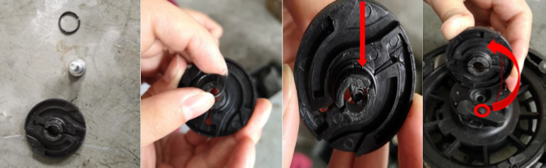
- The bolt can have some locking glue; put the bolt into the through-hole of the press plate and tighten the bolt.
Visual
See below.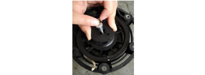
- Secure a stop-knot at the end of the new recoil cover end.
Visual
See below.
- Tighten the bolts and reinstall the recoil handle at the front panel, then loosen the stop-knot. ATTENTION: Do now allow the recoil rope to interfere with the inner wire harness after installation.
Visual
See below.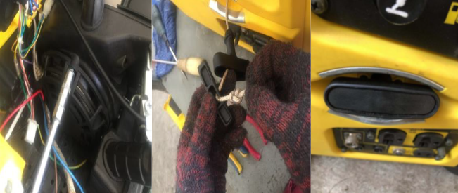
- Reinstall the controller module and rectifier and plug all connectors.
Visual
See below.
- Reinstall the fuel tank and plug the fuel hose onto the carburetor inlet nozzle with the clamp. Reinstall the fuel ON/OFF switch.
Visual
See below.
- Reinstall the rear cover assembly, front cover assembly, and the fuel tank.
Visual
See below.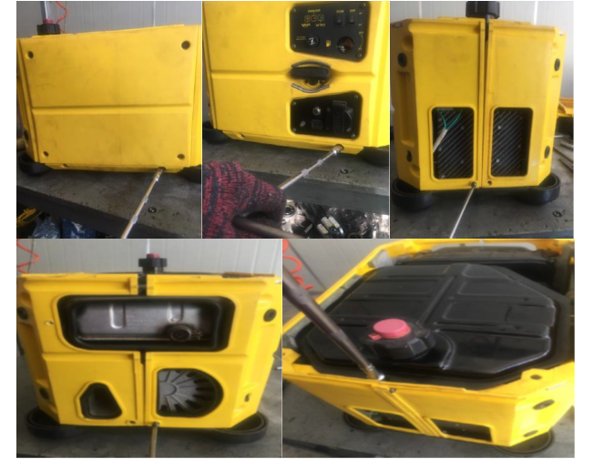
- Reinstall the left cover assembly and the right cover assembly.
Visual
See below.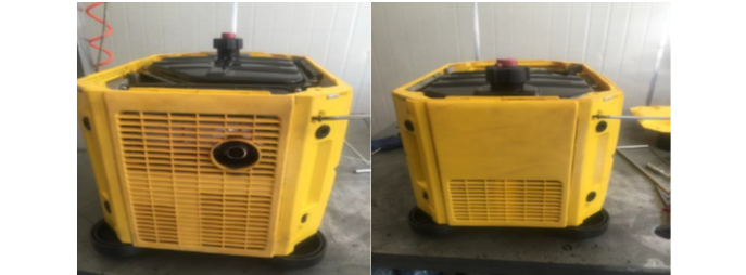
- Reinstall the four corner panels. (Note the orientation of the decorative sheets marked with the "up" arrow). Reinstall the upper cover assembly.
Visual
See below.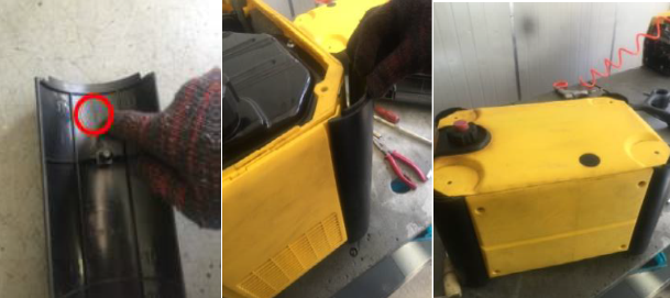
- Reinstall the handle.
Visual
See below.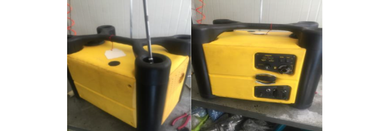
View and download the PDF version here.
How did we do?
Recoil Replacement (Clamshell Inverters)
High Altitude Jet Installation (2,800+ Watt Inverters)