Pump Fails Prime
This bulletin covers the following Champion Power Equipment models: All models that utilize quick-connect hoses. Read instructions carefully and completely performing service. SAFETY PRECAUTIONS. To…
This bulletin covers the following Champion Power Equipment models: All models that utilize quick-connect hoses.
- To reduce the risk of injury, user must read and understand the operator’s manual before using this product.
- DO NOT make any adjustments to the product without first stopping the engine and disconnecting the spark plug wire.
- Burns from hot parts — let the engine cool completely before touching hot parts.
- Injury from moving parts
- To reduce the possibility of fire or explosion, be careful when working around gasoline. Keep cigarettes, sparks and flames away from all fuel‐related parts.
Remove the couple and re-wrap the threaded area of number eight with seven layers of Teflon tape. The tape must be wrapped clockwise as shown. (Pipe Dope can be used instead of Teflon tape.)
Visual
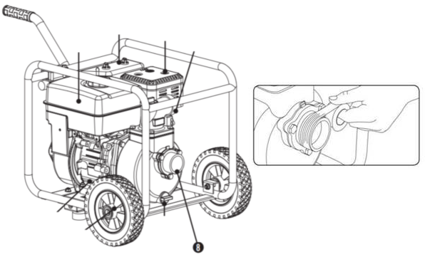
Reinstall the coupler to the pump flange and tighten it with a crescent wrench, combination wrench, pipe wrench, or adjustable pliers. Caveman tight is how tight we want it.
Visual
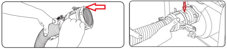
The suction hose and the hose clamp at the coupler must be tightened with a wrench or socket NOT just a screw driver.
Visual

The CAM locks must be fully locked and the levers completely drawn back towards the hose and seated.
Visual

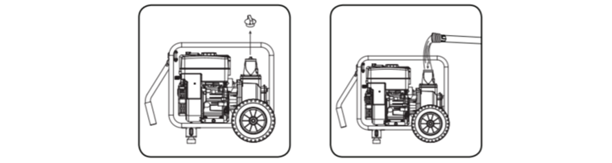
The priming plug needs to be removed and the pump body must be filled to the top before starting the unit to pump.
Visual
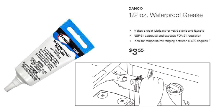
Partially restricting the discharge hose by squeezing or bending it 90 degrees to the outlet flange can help reduce priming time; prime time can be as much as five minutes. If it is still not priming, remove the Quick Connector and put some water soluable grease on the big, black O-Ring that seals between the flange and the coupler.
Visual
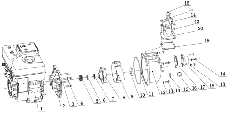
There should not be any leaks between #1 and #2 or around #12 and #18. Any type of leak in these areas indicate a seal or O-Ring failure and a replacement part is required.
Visual
How did we do?
Seal Replacement (Water and Semi-Trash Transfer Pumps)